


As AI demand skyrockets, we’ve had to procure additional capacity fast. Shrinking our regular timelines for new data-center builds means compromising on the kind of reliability we’ve gotten accustomed to. This is not a purely theoretical concern. A few months ago an excavator damaged a power pole, and we were forced to de-energize one of our data centers. Let’s explore the reasons for continuing to allow such a textbook single point of failure to exist, and the tried-and-true mitigations one might apply in the cluster-management layers of our infrastructure.

Data-center evolution
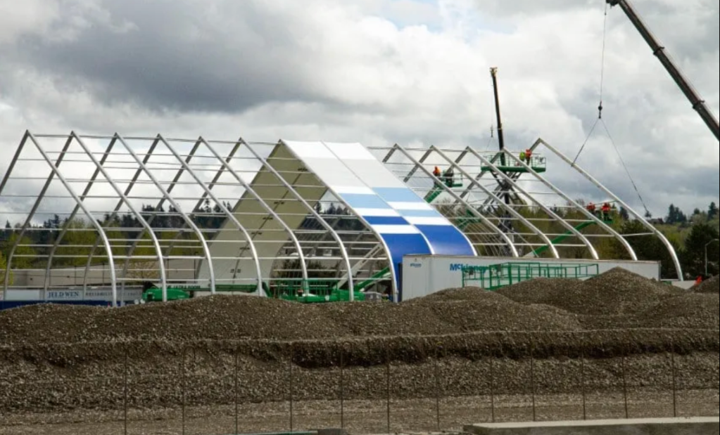
When Meta began building our first data centers almost in 2008, our approach was straightforward. We aimed to construct uniform buildings with appropriate redundancy. Our first designs served user traffic using air cooling (DCType1). That evolved into a mix of air and water cooling. We constructed offline data centers specifically for training purposes and leased more built-to-order facilities. As the demand for computing resources grew, we leased additional data centers to serve our customers. One of the most recent additions, DCTypeT (“tensile-membrane structure”; see Figure 1 below), consists of a simplified physical infrastructure housed in a metal-and-stretched-membrane structure.
The data-center types described above coexist and are connected within larger regions and megaregions, composing larger compute and training clusters.
Infrastructure adoption
Power
A DCTypeT structure is energized by a single, medium-voltage switch, Gear B (MSG-B), illustrated below in Figure 4.
In contrast, DC1 and DC2 buildings are powered by both MSG-A and MSG-B. This setup plays a crucial role in contributing to a cohesive and robust energy-distribution system.
In the event that the MSG-B line-up is de-energized, whether due to scheduled maintenance or an unforeseen failure, the DCTypeT will lose all power. In contrast, both DC1 and DC2 will continue to receive power from the MSG-A, ensuring their operations remain unaffected during such interruptions. (See Figure 6 above.)
If the MSG-A lineup were to be de-energized for a planned or corrective maintenance, MSG-B would be the only power source for all three buildings. But MSG-B is designed to support up to just two buildings at full load. If the amount of power consumed across three buildings exceeds the maximum power that the MSG-B can provide, we may need to shut down one of these buildings (illustrated in Figure 7 below).
Taking down a mature data center like DC1 or DC2 is expected to have a bigger impact because of the many services they host and the reliability commitments in place for those services, so it’s the DCTypeT that would be temporarily shut down in this case.
Network
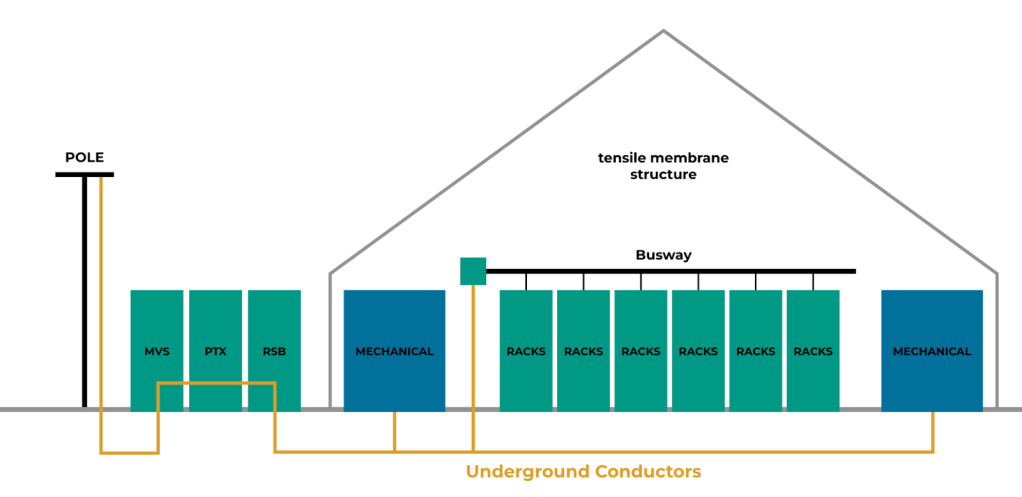
Let’s discuss how network equipment is powered. Poles are used to bring above-ground conductors to our DCTypeT. Damage to any one of these poles or conductors may result in the de-energization of the entire DCTypeT. These poles run alongside the building and connect to medium voltage switches (MVS).
Power flows from an electric pole to various power devices using the underground conductors, and on to the busway and racks. We also power our mechanical load (i.e., cooling equipment) in the same way (see Figure 8).
As shown below in Figure 9, DCTypeT is connected to the rest of the buildings in the region (DC1/2/3/5/6) through spine switches (XSW) located within the structure. The spine switches must remain operational at all times, ensuring seamless connectivity and uninterrupted service across the entire system of buildings.
SSWs within DCTypeT are deployed on two physical rows. Each row contains 50% of the SSW switches. Power is provided to SSW rows by one MVS, one pad-mounted transformer (PTX), and two row switchboards (RSB).
SSWs in our traditional buildings are powered by two different power paths. Loss of any single electrical component is not expected to take down any SSWs, since they can fall back to its secondary power source.
Result
Compared to traditional data centers, DCTypeTs are more susceptible to failure. Here are some examples:
- In March 2022, one of the DCs lost its MSG-A lineup due to a current-transformer failure on the utility side. This caused an explosion at the substation, followed by a fire. It took two days to restore the MSG-A lineup.
- In September 2023, another DC lost both MSG-A and MSG-B lineups due to both substation transformers overheating. It took three months to restore both transformers.
The severity of these failures was immense. Fortunately, when these incidents happened at our traditional data centers, no servers were de-energized, thanks to the redundancy provided by other MSGs. But this severity would be catastrophic to DCTypeTs, as we do not have reliability baked into their design.
Failure domains
A failure domain is a cohort of assets that are susceptible to concurrent failures due to their interdependent connections or common resources, which can greatly affect operational continuity and system integrity.
Identifying and creating an efficient failure domain is important to effectively ensure high levels of reliability, availability, and scalability within data centers and cloud infrastructures, so meticulous design strategies and robust management practices are crucial. This includes implementing redundancy measures, load balancing, and disaster-recovery protocols.
Given the intricate and heterogeneous nature of DCTypeT data-center architectures, along with the pervasive presence of potential single points of failure, selecting the appropriate domain for system deployment becomes a complex and challenging endeavor. Strategic decision-making in this context is vital to mitigate risks and enhance overall resilience.
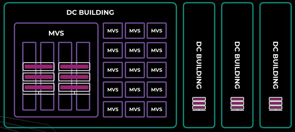
Each DCTypeT is powered with one MSG-B, which provides support to 14 MVS. There are:
- nine MVS providing power to server workloads only
- three MVS providing power to mechanical workloads (including cooling equipment such as fans)
- two MVS providing power to the network for both the front end and back end
- one optional MVS that can be added if we need an additional four rows for either server or backbone-network workloads.
Result
The servers are distributed across multiple MVS, making the establishment of a physical domain unfeasible. Instead, a logical domain needs to be established, while considering the shared dependencies among the components.
To enhance resilience, we have identified 10 distinct failure domains that are strategically arranged across the various MVS. Each of these failure domains is designed to handle a load of 10MW, resulting in a total capacity of 30MW when considering all 10 domains.
Figure 12, below, shows a typical hybrid region with different sizes of failure domain across buildings.

DC1/2 can support 23MW of server racks spread across 12 failure domains. Each failure domain ranges between 1.5MW to 2.5MW.
DC/5/6 can support 30MW of server racks spread across 12 failure domains (FD). Each failure domain is 2.5MW.
DC7 is a DCTypeT which could support 30MW of server racks spread across 10 failure domains. Each failure domain is 3.0MW.
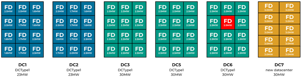
To ensure the reliability tolerance, we can seamlessly allow the loss of a single failure domain without impacting services within the region (see Figure 13 above). For example, if a failure domain (FD) fails in DC6, services are expected to tolerate this capacity loss. This is enabled largely by using a combination of buffers sufficient to cover for capacity loss and placement across failure domains to preserve data availability for stateful systems (e.g., Zippy, MySQL, and others.)
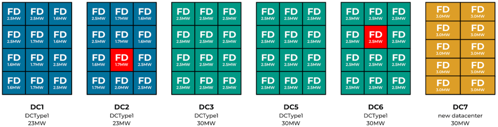
Loss of two failure domains concurrently will likely take down the entire region (see Figure 14 above). We do not provision sufficient buffers to cover for such capacity loss, so stateful services will experience data unavailability. For example, some database shards may have lost two out of three shard replicas, making them unavailable for writes and quorum reads.

With all the single points of failure we have seen earlier with DCTypeT, any such failure is expected to take down 10 failure domains (30MW) worth of capacity concurrently, and this will take down the entire region. (See Figure 15 above.) We do not budget sufficient buffers to cover for a capacity loss of this scale.
Result
All of this means we need innovative software solutions that can effectively utilize this DCTypeT for production purposes, given the lower uptime (see Figure 16 below).

Resilience through placement
To discuss reliability and resilience, it’s useful to begin with the desired objectives. What do we actually want? Is the primary goal to keep the product operating? Keep Facebook, Instagram, WhatsApp, and other apps operational? Or are we focusing on AI training? Each loss scenario would materialize different constraints. Are we okay with a degraded experience? Do we draw the line at permanent data loss? Can we tolerate temporary unavailability or higher latency? What price are we willing to pay for each of these things?
Availability-aware placement
One challenge is the heterogeneity of the environment. Some of the buildings, and some of the hardware, are less reliable. But some are all right. Why don’t we take the things we care about and put them in locations that provide higher availability?
We can certainly try, which requires overcoming a few challenges—but first, your organization has to agree on what the most important things are. Even if you have your business priorities straight, and if you don’t look too closely at any complex multi-tenant services, you still have to reason about the dependencies between the services you support. With thousands of services, some tooling becomes necessary.
Dependency tracking between services can be accomplished by instrumenting RPC frameworks (such as Meta’s ServiceRouter) and tracing tools such as Canopy to build a dependency graph.
The capacity-planning process can be leveraged to capture both the business priorities and, ideally, the dependency contracts between the services.
In terms of priorities, it’s useful to have a plan to gracefully degrade your product features. We use a Defcon system that provides us with structured knobs to turn off certain expensive features to conserve capacity during an emergency.
Finally, remember to test your assumptions. We use disaster recovery exercises known as storms, where we disconnect or power off parts of our infra.
Choose your failure domains wisely
Let’s consider the potential blast radius of an MVS failure. In the worst case, an MVS outage would affect power to the mechanical load—fans, cooling, and pumps. That would put the whole DCTypeT out of commission, corresponding to roughly 25% regional capacity loss in some regions. If the DCTypeT hosted a critical chunk of core services, the event would escalate into a regional failure due to the loss of the control plane for the region. A large regional outage may exceed the replication tolerances of the megaregion storage fabric, bringing down the training workloads in the entire megaregion. We aim to avoid such cascading failures, in which the failure of one small component puts a larger domain at risk (shown in Figure 17).
Let’s look at one of the core services that may have contributed to the escalating failure in our scenario. Control-plane systems often require a consistent data store. At Meta, this role is filled by Zelos—a reliable, consistent, and highly available storage system, equivalent to Apache ZooKeeper. A Zelos ensemble is deployed with five replicas, and we need at least three of them to be up for Zelos to function.
In the first strawman scenario, let’s settle on an MVS as the failure domain (see Figure 18). Spreading wide between the failure domains results in each Zelos replica being placed in a different MVS. After one MVS failure, we are left with four healthy replicas. Under normal circumstances, we budget a failure buffer equal to the largest failure domain within a region. That buffer can now be used to host the lost replica, restoring the full five replicas of the ensemble. This setup is not resilient to failures larger than the chosen domain (e.g., a building failure).
Let’s consider spreading across buildings. In this particular data-center region, we only have four buildings, and so two replicas will have to share one failure domain. In case of an outage of that failure domain, we still maintain a functional ensemble with the remaining three replicas. We can’t allow any more replicas to go offline until the two lost replicas are restored—and that also limits our ability to update the remaining replicas in place.
We can avoid a cascading failure by setting correct placement constraints and containing failures within selected failure domains. This is obviously not a new technique. It’s an existing system of constraints that we adopt to work in a new environment. The choice of a failure domain is a tradeoff between multiple factors, including:
- failure frequency—that depends on the data center design and hardware,
- the number of failure domains that you need—which mostly depends on your software requirements,
- and the cost of overheads and replacement buffers.
For example, it’s advisable to fund buffers and set large failure domains for critical pieces of infrastructure running on relatively cheaper hardware. Doing the same for GPUs may prove too costly and will require mitigating risks by using smaller failure domains, preventing cascading failures by aligning the failure domains with training units.
Moving containers around
With correct abstractions, we can build tooling that places things correctly and avoids putting all the replicas in one basket, as we saw above. The key element is the flexibility Cluster Management has to move containers around. If the service owners were allowed to pin their workloads to a specific server, a specific DC building, or a specific region, that flexibility would be kneecapped.
We want our engineers to avoid being too specific in how they determine placement, and to use higher-level constraints that allow us to move workloads around. This is classically done with abstractions such as “regions” or “availability zones.” We find that unless correct Cluster Management abstractions and incentives are put in place, the engineers may choose overly restrictive placement, which may be locally optimal but detrimental to the infrastructure as a whole. A spectrum of options needs to be addressed. For a small number of hardware experimentation use cases, pinning to specific servers may be necessary. For latency-sensitive workloads, colocation constraints of different scopes can be provided. Others require regional or megaregional constraints, and some are truly global and can be placed anywhere. With correct abstractions, Twine (our container-management system) can move eligible workloads to other regions.
Enabling failover movement between regions adds megaregion-level resiliency on top of the regional resiliency we’ve discussed.
What’s next?
We have talked about our remarkable journey of transforming a vacant plot of land with an available substation power into an impressive hub that not only supports our expansion but also powers a cutting-edge AI training cluster! Now, let’s dive into the thrilling plans we have lined up for the next few years to supercharge our support for the booming world of AI.
Figure 20: Exponential growth of regions
First and foremost, our commitment to expansion translates into the establishment of additional data centers. Let’s quantify what that tremendous growth means. At the close of last year, our training cluster boasted an impressive size of 129K, powered by 166MW of energy. But that’s just the beginning! As we propel ourselves into the future, we’re not only upgrading our GPUs from H100 to GB200, which will enhance performance, power efficiency, and memory bandwidth, but also gearing up for a game-changing transformation. (See Figure 21 below.) We’re setting our sights on a massive 2-4GW cluster, equipped with the very latest GPUs available at that time. That’s a staggering 31 times the capacity we currently hold.
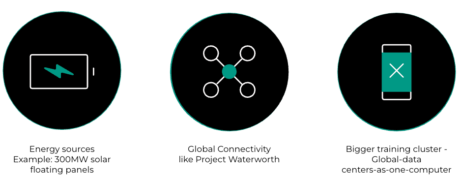
As we set our sights on ambitious growth, it’s clear that merely building data centers and innovating within them isn’t enough. We’re ready to break free from the ordinary and revolutionize the ecosystems around us. We’re on the cutting edge of energy innovation,creating our very own energy through solar panels to power our data centers. Plus, we are exploring various approaches to address the hunger for more power by leveraging natural gas options as well.
And we won’t stop there. Our groundbreaking initiative, Project Waterworth, will establish a next-generation subsea infrastructure that spans over 50,000 kilometers, dramatically enhancing global connectivity!
Our machine-learning training is evolving rapidly. From its humble beginnings with a single GPU under a desk, we’re now orchestrating massive training efforts across racks, data centers, and entire regions filled with GPUs, compute, and storage working in harmony. We’re shifting gears from thinking of the “data-center-as-computer” to embracing the exhilarating idea of “all-data-centers-as-a-computer!”

